Search

Custom Search

Tuesday, March 10, 2009

Centrifugal pumps for chemical applications

Horizontal single-stage end-suction overhung impeller centrifugal pumps (for chemical applications includes ISO 2858, ISO 3069, ISO 3661, ASMEIANSI B73.1 designs)

ANSI, the American National Standards Institute, has a philosophy more similar to DIN than ISO in that it specifies materials and mechanical seal options. B73.1 is a standard for single stage centrifugal pumps, with back pull-out, intended for chemical and corrosive duties.  The Standard specifies bareshaft pump dimensions, also installation dimensions for complete packages with motor and baseplate. The Standard does not specify hydraulic duties. Mechanical seal arrangements, with various piping plans, are detailed to cover most applications. Depending upon materials and cooling arrangements pumpsmust be suitable for at least 260 deg. C.

Wednesday, March 4, 2009

IEC vs NEMA enclosure

NEMA Standards Enclosures for Electrical Equipment (1000Volts maximum) comparison to IEC 60529 Degrees of Protection provided by Enclosure IP Classification designation (cannot be used to convert IEC classification designations to NEMA type numbers)

NEMA Enclosure Type Number              IEC Enclosure Classification
                       1                                                                 IP 10
                       2                                                                 IP 11
                       3                                                                 IP 54
                       3R                                                              IP 14
                       3S                                                               IP 54
                       4 and 4X                                                    IP 56
                       5                                                                 IP 52
                       6 and 6P                                                    IP 67
                       12 and 12K                                                IP 52
                       13                                                               I P 54"

Saturday, February 21, 2009

Hazardous Environment - Motors

Atmospheres can be classified as:

* Non-explosive atmosphere; the atmosphere does not contain explosive elements and all types of standard products can be used.
* Explosive atmosphere; the atmosphere does contain potentially explosive elements, either gas or dust.
Explosive atmosphere is referred to as 'Hazardous area' in IEC countries and 'HAZLOC' in North America

Equipment for explosive atmosphere is designed, installed, operated and maintained according to International standards and local regulations dedicated to this area.

Hazardous Area or Location is defined by 4 elements:
* Class
* Zone
* Group
* Temperature Class


Explosive atmosphere

The relevant parameters below characterize the potentially explosive atmosphere:

* Frequency with which potentially explosive atmosphere may exist
* Capability of gas or dust atmosphere to create an explosion

Explosive gas and dust is classified according to its likelihood to be ignited, according to its characteristics:

* Minimum ignition energy
* Minimum ignition temperature
* Auto-ignition temperature
* Layer ignition temperature"

Friday, February 20, 2009

Converting Pump Head to Pressure

Converting head in feet to pressure in psi
Pump curves in feet of head can be converted to pressure - psi - by the expression:

p = 0.434 h SG (1)

where
p = pressure (psi)
h = head (ft)
SG = specific gravity

Converting head in meter to pressure in bar
Pump curves in meter of head can be converted to pressure - bar - by the expression:

p = 0.0981 h SG (2)

where
h = head (m)
p = pressure (bar)

Converting head in meter to pressure in kg/cm2
Pump curves in meter of head can be converted to pressure - kg/cm2 - by the expression:

p = 0.1 h SG (2b)

where
h = head (m)
p = pressure (kg/cm2)

Converting Pressure to Head

Since pressure gauges often are calibrated in pressure - psi or bar, it may be necessary with a conversion to head - feet or meter, commonly used in pump curves.

Converting pressure in psi to head in feet

h = p 2.31 / SG (3)

where
h = head (ft)
p = pressure (psi)

Converting pressure in bar to head in meter

h = p 10.197 / SG (4)

where
h = head (m)
p = pressure (bar)

Converting pressure in kg/cm2 to head in meter

h = p 10 / SG (4b)

where
h = head (m)
p = pressure (kg/cm2)

Motor Enclosures

The selection of a motor enclosure depends upon the ambient and surrounding conditions. The two general classifications of motor enclosures are open and totally enclosed. An open motor has ventilating openings which permit passage of external air over and around the motor windings. A totally enclosed motor is constructed to prevent the free exchange of air between the inside and outside of the frame, but not sufficiently enclosed to be termed air-tight.

These two categories are further broken down by enclosure design, type of insulation, and/or cooling method. The most common of these types are listed below.

Open Dripproof - An open motor in which all ventilating open-ings are so constructed that drops of liquid or solid particles falling on the motor at any angle from 0 to 15 degrees from vertical cannot enter the machine. This is the most common type and is designed for use in nonhazardous, relatively clean, industrial areas.

Encapsulated - A dripproof motor with the stator windings com-pletely surrounded by a protective coating. An encapsulated motor offers more resistance to moisture and/or corrosive en- vironments than an ODP motor.

Totally Enclosed, Fan-Cooled - A enclosed motor equipped for external cooling by means of a fan integral with the motor, but external to the enclosed parts. TEFO motors are designed for use in extremely wet, dirty, or dusty areas.

Explosion-Proof, Dust-Ignition-Proof - An enclosed motor whose enclosure is designed to withstand an explosion of a specified dust. gas, or vapor which may occur within the motor and to prevent the ignition of this dust, gas, or vapor surrounding the motor. A motor manufacturer should be consulted regarding the various classes and groups of explosion-proof motors avail-able and the application of each.

Motor insulation is classified according to the total allowable temperature. This is made up of a maximum ambient temperature plus a maximum temperature rise plus allowances for hot spots and service factors. Class B insulation is the standard and allows for a total temperature of 130 degrees C. The maximum ambient is 40 degrees C, and the temperature rise is 70 degrees C, for ODP motors and 75 degrees C for TEFC motors."

Net Positive Suction Head (NPSH) and Cavitation

The Hydraulic Institute defines NPSH as the total suction head in feet absolute, determined at the suction nozzle and corrected to datum, less the vapor pressure of the liquid in feet absolute. Simply stated, it is an analysis of energy conditions on the suction side of a pump to determine if the liquid will vaporize at the lowest pressure point in the pump.

The pressure which a liquid exerts on its surroundings is dependent upon its temperature. This pressure, called vapor pressure, is a unique characteristic of every fluid and increased with increasing temperature. When the vapor pressure within the fluid reaches the pressure of the surrounding medium, the fluid begins to vaporize or boil. The temperature at which this vaporization occurs will decrease as the pressure of the surrounding medium decreases.

A liquid increases greatly in volume when it vaporizes. One cubic foot of water at room temperature becomes 1700 cu. ft. of vapor at the same temperature.

It is obvious from the above that if we are to pump a fluid effectively, we must keep it in liquid form. NPSH is simply a measure of the amount of suction head present to prevent this vaporization at the lowest pressure point in the pump.

NPSH Required is a function of the pump design. As the liquid passes from the pump suction to the eye of the impeller, the velocity increases and the pressure decreases. There are also pressure losses due to shock and turbulence as the liquid strikes the impeller. The centrifugal force of the impeller vanes further increases the velocity and decreases the pressure of the liquid. The NPSH Required is the positive head in feet absolute required at the pump suction to overcome these pressure drops in the pump and maintain the majority of the liquid above its vapor pressure. The NPSH Required varies with speed and capacity within any particular pump. Pump manufacturer's curves normally provide this information."

Thursday, February 19, 2009

Specific Speed and Pump Type

Specific speed (Ns) is a non-dimensional design index used to classify pump impellers as to their type and proportions. It is defined as the speed in revolutions per minute at which a geometrically similar impeller would operate if it were of such a size as to deliver one gallon per minute against one foot head.

The understanding of this definition is of design engineering significance only, however, and specific speed should be thought of only as an index used to predict certain pump characteristics. The following formula is used to determine specific speed:


Where
N = Pump speed in RPM
Q = Capacity in gpm at the best efficiency point
H = Total head per stage at the best efficiency point

The specific speed determines the general shape or class of the impeller as depicted in Fig. 3. As the specific speed increases, the ratio of the impeller outlet diameter, D2, to the inlet or eye diameter, Di, decreases. This ratio becomes 1.0 for a true axial flow impeller.

Radial flow impellers develop head principally through centrifugal force. Pumps of higher specific speeds develop head partly by centrifugal force and partly by axial force. A higher specific speed indicates a pump design with head generation more by axial forces and less by centrifugal forces. An axial flow or propeller pump with a specific speed of 10,000 or greater generates it's head exclusively through axial forces.

Radial impellers are generally low flow high head designs whereas axial flow impellers are high flow low head designs.

Values of Specific Speed, Ns

PAPER STOCK PERCENT CONSISTENCY

The consistency of a pulp and water suspension is the percent by weight of pulp in the mixture. Oven Dry (O.D.) consistency is the amount of pulp left in a sample after drying in an oven at 212?F. Air Dry (A.D.) consistency is an arbitrary convention used by paper-makers, and is the amount of pulp left in a sample after drying in atmosphere. Air Dry stock contains 10% more moisture than Bone Dry stock, i.e. 6% O.D. is 6.67% A.D."

Tuesday, February 17, 2009

API 610 Power rating for motor drives


Pump selection and quality considerations

The following conditions should (explicitly or implicitly) be known in view of correctly selecting a pump:

  1.  task of the pump in the system.
  2. The system pressure and temperature.
  3. Data for rated performance: QR, HR,tot. Often rated performance equals the guaranteed point Qg, Hg. The rated and/or guaranteed performance may beidentical to the BEP (but this is not necessarily so).
  4. The NPSHA of the plant at rated, guaranteed or BEP conditions and, as necessary,at other operation conditions.
  5. Performance data for other specific operation points (if necessary).
  6. The maximum and minimum flow rates in the domain of continuous operation.
  7. The maximum and minimum flow rates during short-term operation or in transient conditions, e.g. during a switch-over of parallel working pumps, at load rejection or other.
  8. . For pumps operating in parallel the maximum flow rate (run-out) is determined by the operation of a single pump. At run-out the available NPSHA must be sufficient to prevent excessive cavitation.
  9. When pumps are installed in series, their interaction has to be analyzed with regard to control and upset conditions such as one pump falling out of service.
  10. The type and the chemical composition of the medium to be pumped, in particular corrosive substances.
  11. The physical properties of the pumpage if it is any other than water or a common, clearly defined medium. In this case the vapor pressure must be correctly specified in order to ensure that the effects and risks of cavitation can be assessed.
  12. Viscosities appreciably above that of cold water need corrections for Q, H, P,η and NPSH .
  13. Possible inclusions of free gas or dissolved gases that might separate from the liquid in the suction pipe.  The available NPSHA must be selected so that the volume fraction of free gas at the impeller inlet is below typically 2 to 4% at low suction pressures.
  14. Possible inclusions of solids (abrasion).
  15. The type of driver (electric motor, turbine, combustion engine).
  16. Fixed or variable speed? Speed range, if applicable.
  17. Is a gear box necessary?
  18. What kind of control is intended?
  19. How much standby capacity is required (e.g. 2x100% or 3x50% pumps)?
  20. Operation mode: Continuous or short-term operation? Cyclic operation with frequent start-ups and shut-downs?
  21. Installation conditions: Horizontal or vertical arrangement?
  22. Approach flow or suction conditions: Open or closed circuit? Open pit?
  23. Fluid level variations in the suction and discharge reservoirs or pressure variations on the suction and discharge side of the pumping system.
  24. The system characteristic or at least its static part Hstat resulting from the geodetichead differences and/or the pressure differences between the suction tank and the discharge vessel.
  25. Are there any special requirements concerning the head-capacity characteristic (steepness, head rise, shut-off pressure)?
  26. The maximum admissible shut-off pressure with the allowed tolerance, if applicable.
  27. For correctly sizing the driver, the maximum power consumption must be determined; with a small specific speed it occurs at about the maximum flow rate, with a medium nq near the BEP, and with very high specific speeds at shut-off.
  28. Are there any special requirements regarding vibrations or noise? Have limits been specified for the sound level?.
  29. What tolerances are permitted for manufacturing and measurements? Which standard is to be applied for the acceptance test?
  30. The guarantee and acceptance conditions, including possible penalties on efficiency or power consumption
  31. The operation period per year and the energy costs (e.g. $/kWh) or an assessment of the capitalized energy costs (e.g. $/kW). Minimization of the energy costs per year according to the intended operation scenarios.
  32. Safety considerations, explosion protection, zero-leakage to environment, ecological aspects.


Monday, February 16, 2009

Electric Motor Speed


The speed of an AC electric motor is determined by the frequency of the supply and the number of poles in the motor stator according to the following relationship:

where
n = speed (r/min)
f = supply frequency (Hz)
p = number of stator poles

From equation it can be seen that a change in frequency causes a change in speed. Electric motors can thus be speed regulated by means of varying the frequency

In Europe the frequency is 50 Hz, therefore the speed of electric motors is 6000 divided by the number of poles. At least two poles are required which produces a maximum speed of 3000r/min; 4 poles gives 1500; 6 gives 1000; 8 gives 750 r/min, etc. In the US and some Middle East countries as mentioned, the frequency is 60 Hz.

NPSH

Pump NPSH Requirement (NPSHR)
This figure is the necessary amount of energy required (measured in metres) in the liquid at the pump inlet to overcome the internal losses/resistances within the pump and provide sufficient internal pressure to avoid cavitation. These losses are caused by the flow of liquid through the pump suction passage and the shock loss which occurs at the impeller blade. The NPSHR is calculated by the pump manufacturer and will vary depending on the size and speed of the pump.

Available NPSH (NPSHA)
The available NPSH (NPSHA) is the amount of energy (measured in m) available to the fluid at the pump inlet after the factors from section 1 have been taken into account. For a pump to run the NPSHA value must be greater than the NPSHR value. The NPSHA value will govern the amount of suction lift which may be attained with a given pump or the amount of static suction head which is required above pump suction to ensure correct operation.

Hydraulic power

If a pump were an ideal machine, the required input power to drive the pump would
entirely lift the mass flow rate from one elevation to another. This power is called as the
hydraulic power.

Where
Q= capacity in m3 /h
ρ= liquid density in kg/m3 at pumping temperature
H= differential head in m (meters of liquid column)
g= gravitational acceleration in m/s .

Newtonian Fluid

A fluid is classified as being Newtonian if it conforms to NEWTON’s friction law, i.e. if viscosity remains constant with agitation or varying shear rate (i.e. viscosity is only affected by temperature changes) and its shear rate being proportional to the velocity gradient vertical to the direction of flow.

Of Newtonian fluid characteristics are e.g. the following:

water
oils
gases
mercury
alcohol
petrol

If it is not known whether a fluid is of Newtonian flow characteristics or not, it should be laboratory-tested."

Friday, February 13, 2009

Couplings Type


Couplings for pumps usually fall in the category of general-purpose couplings. General purpose couplings are standardized and are less sophisticated in design. The cost of such coupling is also on the lower side. In addition, there are special purpose couplings that can be used on turbo machines and are covered by the API 671 specification.

In these couplings, the flexible element can be easily inspected and replaced. The
alignment demands are not very stringent. The couplings fitted on pumps usually fall inany of the five types mentioned below.
These are:
1. Gear coupling
2. Grid coupling
3. Disk coupling
4. Elastomeric compression type
5. Elastomeric shear type.

Seismic Survey


The most accurate and widely used means of finding good drilling locations is the seismic survey. Seismic surveying involves sending sound waves down into the ground and recording the echoes that bounce back off the various sedimentary layers.The sound or shock waves are generated by; setting off small explosive charges just below the surface; hitting the ground with a heavy weight; or shaking the ground using large vibrator trucks. The echoes returning from the subsurface are detected by sensitive instruments called geophones which are strung out along the ground in a straight line. The geophones are connected by electrical cable to a recording system. The recording system precisely records, to the nearest one thousandth of a second on magnetic tape, the time it takes for the echoes to return to the surface. By knowing the amount of time it takes for a sound wave to reach a certain layer and then bounce back to the surface, as well as the speed of sound through the rock
layers in between, the geophysicist is able to determine the depth to that layer at that location. By determining the depth at a large number of points along the seismic line, the geophysicist is able to create a profile of the underground layers along the line.

Pump System Life Cycle Cost Reduction

The primary objective of life cycle costing is to evaluate and/or optimize product life cost while satisfying specified performance, safety, reliability, accessibility
maintainability, and other requirements. Pumping systems account for an estimated 25%-50% of the energy usage in many industrial plants, and perhaps 20% of the world’s electric energy demand. Centrifugal pumps rank first in failure incidents
and maintenance costs. That is why centrifugal pumps in critical applications are installed in identical pairs, one serving as the operating, the other one serving as the standby or spare pump. Despite these statistics, many pump purchase decisions
are still made solely on the basis of lowest initial purchase and installation cost. The notion exists that, if a cheap pump doesn’t perform well, it can always be
upgraded. While this may be true in those pumps that suffer from installation errors or component defects, it is not true for pumps that suffer from fundamental design
compromises. Moreover, these decisions seem to disregard that initial purchase price is generally only a small part of pump life cycle cost in high usage applications.
Market conditions, short-term financial considerations, and organizational barriers are to blame for this shortsighted approach.

LCC = Cic + Cin + Ce + Co + Cm + Cdt + Cenv + Cd
where:
LCC = Life Cycle Cost
Cic = Initial Cost, purchase price (pump, system,
pipe, auxiliary services)
Cin = Installation and commissioning cost
Ce = Energy costs (pump, driver & auxiliary services)
Co = Operation costs
Cm = Maintenance and repair costs
Cdt = Down time costs
Cenv = Environmental costs
Cd = Decommissioning and/or disposal costs

Thursday, February 12, 2009

Wellhead


The wellhead is equipment used to maintaain surface control of the well. It is usually made of cast or forged steel and machined to a close fit to form a seal and prevent well fluids from blowing or leaking at the surface.

Flange Standards

There are a variety of standards used in the design and selection of flanges. The
following codes and standards relate to pipe flanges:
ASME Codes and Standards:
B16.1 Cast Iron Flanges and Flanged Fittings
B16.5 Pipe Flanges and Flanged Fittings
B16.24 Bronze Flanges and Fittings–150 and 300 Classes
B16.42 Ductile Iron Pipe Flanges and Flanged Fittings–150 and 300 Classes
B16.47 Large Diameter Steel Flanges

Tuesday, February 10, 2009

Shaft couplings

A shaft coupling transfers torque between two in-line, or nearly in-line, rotating shafts. The magnitude of the torque in the shafts is equal, although slipping and disengagement can cause speed variations. In its simplest, and perhaps oldest form, the coupling acts as a means of joining shafts. Another function is to join two shafts which are not necessarily in perfect alignment with each other. The coupling in this case must be capable of absorbing such misalignment. Modern couplings,
between pump and driver, must be capable of rapid disassembly.

Baseplates

Pump units are mounted on baseplates to allow the unit to be bolted down. Unless otherwise stated, baseplates are designed for mounting on concrete foundations and to be supported over the whole length by grouting. The pump supplier must be aware if a baseplate is intended for mounting on structural steelwork with intermittent supports. The design of the baseplate side members may need adjusting to preserve alignment. If the baseplate is to be grouted in with epoxy grout rather than concrete, a special paint finish will be required on the contact surfaces. If the baseplate is to be welded down to structural steelwork the pump supplier should be informed.

Pump efficiency

The pump does not completely convert kinetic energy to pressure energy since some of the kinetic energy is lost in this process. Primarily, there are three areas where this energy is dissipated and not converted to useful work. Pump efficiency is a factor that accounts for these losses. Pump efficiency is a product of the following three efficiencies:

1. Hydraulic efficiency
(primarily, disk friction, which is the friction of the liquid with the impeller shrouds. This is a function of speed and impeller geometry. Other losses are shock losses during rapid changes in direction along the impeller and volute)

2. Volumetric efficiency
(recirculation losses at wear rings, interstage bushes and other)

3. Mechanical efficiency
friction at seals or gland packing and bearings). Some texts call the product of the first two efficiencies as internal efficiency of the pump. Every pump is designed for a specific flow and a corresponding differential head, though it is possible to operate at certain percentage points away from the designed values. However, the efficiency of the pump at the designed point is maximum and is called as the BEP. Efficiency at flows lower or higher than this design point is lower. The efficiency of the pump has a close relationship to an important pump number called as the specific speed.

Sunday, February 8, 2009

Pump Priming System

FOOT VALVES
A foot valve is a form of check valve installed at the bottom, or foot, of a suction line.When the pump stops and the ports of the foot valve close, the liquid cannot drain back to the suction well if the valve seats tightly. Foot valves were very commonly used in early installations of centrifugal pumps. Except for certain applications, their use is now much less common.

PRIMING CHAMBERS
Chamber primer is a tank with a bottom outlet thatis level with the pump suction nozzle and directly connected to it. An inlet at the top of the tank connects with the suction line. The size of the tank must be such that the volume contained between the top of the outlet and the bottom of the inlet is approximately three times the volume of the suction pipe. When the pump is shut down, the liquid in the suction line may leak out, but the liquid in the tank below the suction inlet cannot run back to the supply. When the pump is started, it will pump this entrapped liquid out of the priming chamber, creating a vacuum in the tank. The atmospheric pressure on the supply will force the liquid up the suction line into the priming chamber.

PRIMING INDUCTORS
If a separate source of liquid of sufficient capacity and pressure is available, it can be used to fill the suction line of the pump to be primed through the use of an inductor. For water, the pressure must be equal to about 4 lb/in2 for each foot (90 kPafor each meter) of head necessary to prime the pump, measured from the lowest liquid level in the sump from which priming must be accomplished to the top of the pump. The amount of liquid necessary depends on the pressure.

CENTRAL PRIMING SYSTEMS
If there is more than one centrifugal pump to be primed in an installation, one priming device can be made to serve all the pumps. Such an arrangement is called a central priming system. If the priming device and the venting of the pumps are automatically controlled, the system is called a central automatic priming system.

Slurry Pump

Mine Dewatering Pump

What should we consider to select or design "Mine Dewatering Pump" ?
- Liquid properties (solid content, solid size, abrasive?, corosive?)
- Make sure about suction condition (negative? we'll need priming system)
- Pump driver (we'll need independent power source; diesel engine; generator set)
- pump skid (skate board, ponton, etc)

Killing Well Pump

- High pressure triplex plunger pump can be use for killing well pump
- Flow rate can be control by adjust pump speed or bypass the pump flow

Pumps for Educational Organizations


IMO Pump :

"From time to time, we have surplus or prototype pumps for which we no longer have a need. Rather than scrap them, when available, we will donate them to any educational organization requesting one on a first come basis. These pumps would generally be small three screw pumps or small high pressure gear pumps. If interested, please mail a business card to Jim Brennan, Imo Pump, P. O. Box 5020, Monroe, NC 28111-5020 USA. Shipments outside the USA will be freight collect."

Allweiler® pumps from Colfax help keep Hermann Bantleon operations running smoothly


Challenge:
Germany’s Hermann Bantleon GmbH,one of the world’s leading producers and suppliers of lubricants, relies on a combination of speed, flexibility and superior customer
service to deliver both universal and customized product lines to its customers
around the globe. That means operating a wide array of pump types and sizes to
maximize the efficiency of the company’s manufacturing processes.

Solution:
For nearly 30 years, Bantleon has relied on Allweiler AG of Radolfzell, Germany,
for all of its pumping demands. Over those years Allweiler has successfully supplied
different pump types, regardless of the specific pumping task. Sometimes capacity
is a critical factor in selecting a pump for a specific application; other times it’s the type of liquid to be pumped.

Results:
Today Bantleon is able to obtain all of the pumps that it needs from a single source
and with just one contact for sales and service. In total about 80 Allweiler® pumps
are installed at the company’s Ulm location. Seventy of those are screw pumps for
lubricating liquids. Approximately 10 pumps used to move easily combustible
liquids like solvents are installed in explosion-proof versions.

Working To Meet Customer Demands
The development, production and sale of lubricants is a major business segment at Hermann Bantleon GmbH. At its plant in Ulm,Germany, Bantleon begins with high-quality base oils and produces both universal and customized lubricants, according to its own formulas. Customized products are often the best way to meet special
customer requirements in both cutting and noncutting production processes. Bantleon also works to meet customer demands by improving its efficiency and quality-assurance systems. The company mixes additives to a variety of base oils, according to internally developed formulas. It then pulls retained samples from every batch and tests them in Bantleon’s own laboratory, before delivering products to customers.

Time-Tested Pumping Solutions
In addition to providing improved efficiency and superior product quality, Bantleon relies on fast reaction times and flexibility as vital elements of its customer-service capabilities. To deliver that speed and flexibility, the company counts on a wide range of pump types and sizes to play a major role in its manufacturing processes. Allweiler has been meeting those varied application demands for nearly three decades. In fact, nearly 40 SNH Series screw pumps have been in service in Bantleon’s base-oil tank farm over the past 30 years. And, incredibly, not one of the pumps has failed for an extended period of time or required repair during those three decades.

The Right Pump for the Right Job
Bantleon demands different pump types, depending on the specific pumping tasks required. Sometimes the lubricant’s capacity is the critical selection factor; sometimes it is the type of liquid that must be pumped. For example, moving nonlubricating or poorly lubricating liquids like antifreeze requires the use of side-channel pumps. Centrifugal pumps are ideal for clean lubricating liquids. Progressing cavity pumps and peristaltic pumps are better suited for contaminated
liquids, such as used oil. Peristaltic pumps are mostly used for moving used oil in systems at customer sites, because they can run dry, making them suitable for unsupervised operation. And small progressing cavity pumps work best for precisely metering and adding potentially expensive additives. Bantleon must be able to meet the requirements of each of these specific applications, either in its own roduction and filling plants or as part of its full line of services. Accordingly Allweiler AG offers these pump types, accompanied by a wide range of services, like recommending the right pump technology for the right application, as well as calculating and recommending expected NPSH requirements,friction losses and right pile diameter. This combination results in trouble-free and economical operation of the pump and allows Bantleon to obtain all of the pumps that it needs from a single
source, with just one contact for sales and service. Recently a new filling station required Bantleon to provide two AEB Series progressing cavity pumps, to precisely meter high-viscosity additives (up to 6,300 square millimeters per second [mm2/sec.] at 65 degrees Celsius liquid temperature), as well as four NT Series centrifugal pumps capable of moving 30 cubic meters (m3) of base oils at a temperature of 20 degrees Celsius. Depending on the liquid, pumps at Bantleon must be able to handle a viscosity range of between two and 10,000mm2/sec. In total about 80 Allweiler pumps
are installed at the company’s Ulm location. Seventy of those are screw pumps for lubricating liquids. Approximately 10 pumps used to move easily combustible liquids like solvents are installed in explosion-proof versions (ATEX). Nearly one million liters of lubricant are stored in the 80 tanks. Yearly pump throughput is proximately
15 million liters.

Building a Productive – and Profitable – Relationship
At Bantleon a long service life, low investment cost and high availability are major criteria for choosing a pump. But the long and excellent relationship between the two companies remains a key reason that Bantleon continues to purchase its new pumps from Allweiler. This holds true for pumps needed to expand its own production capabilities, as well as for plants that Bantleon constructs for its customers.
Compliance with environmental and worker-protection regulations is another important business consideration. So for Bantleon, it is not enough for the pump manufacturer to simply deliver high-quality pumps. Even more important, the pumps supplied must be able to take advantage of standardized procedures, allowing Bantleon to quickly and easily select the right pump for the job. Rainer Janz, responsible for product and quality management at Hermann Bantleon GmbH, says,“The pumps that we get from Allweiler exhibit consistently high quality; this gives us very high process stability and virtually no downtime.”These benefits go straight to the company’s bottom line, because backup pumps are unnecessary. Finally, Bantleon values superior
design. Allweiler pumps have excellent NPSH values (less than 3m),so that long piping and deep tanks ensure adequate reserves for pressure losses.According to Dieter Schrag, shop and production foreman of Hermann Bantleon GmbH, “Bantleon and Allweiler have had a very strong customer-supplier relationship for several decades. Our company started ordering Allweiler pumps back in the 1970s and 1980s. Obviously my colleagues made a good choice back then. We have found no reason to switch suppliers. We have always been satisfied with the pumpsand the support.”

Sulzer and Saudi Aramco Sign a Strategic Ten Year Supply Agreement

Sulzer announced today that it is the first company to negotiate and sign a Strategic Corporate Procurement Agreement (CPA) with Saudi Aramco, the world's largest oil producing company. The agreement was signed in the Kingdom of Saudi Arabia by Ton Büchner, CEO Sulzer and Kim Jackson, President Sulzer Pumps.


In a bid to simplify the procurement process, Saudi Aramco has embarked on an ambitious program of determining best business practices and commercial terms with all its key suppliers. The agreement with Sulzer is the first, and additional agreements with other companies are expected in the coming months.

The agreement covers the supply of products, system solutions, and services from all Sulzer divisions to Saudi Aramco for a 10-year period. Sulzer and Aramco have a long standing business relationship, and both companies feel that by moving to this higher level of cooperation greater efficiency gains may be achieved.

This is of particular importance as Saudi Aramco continues its high level of capital investment in both upstream and downstream projects in the oil and gas market.

Sulzer is looking forward to using the agreement as a future trading platform with Saudi Aramco and its partners.

Saturday, February 7, 2009

API Std 674 Positive Displacement Pumps - Reciprocating

Covers the minimum requirements for reciprocating positive displacement pumps for use in petroleum, chemical, and gas industry services. Both direct-acting and power-frame types are included.

Pump Standard API 676

the minimum requirements for rotary positive displacement pumps for use in the petroleum, chemical, and gas industries. It provides a purchase specification to facilitate the manufacture and purchase of rotary positive displacement pumps.

Centrifugal Pump Affinity Laws

The Affinity Laws of centrifugal pumps or fans indicates the influence on volume capacity, head (pressure) and/or power consumption of a pump or fan due to
change in speed of wheel - revolutions per minute (rpm)
geometrically similarity - change in impeller diameter

Note that the affinity laws for fans are not identical with pumps.
Pump Affinity Laws
Volume Capacity

The volume capacity of a centrifugal pump can be expressed like

q1 / q2 = (n1 / n2)(d1 / d2) (1)

where

q = volume flow capacity (m3/s, gpm, cfm, ..)

n = wheel velocity - revolution per minute - (rpm)

d = wheel diameter
Head or Pressure

The head or pressure of a centrifugal pump can be expressed like

dp1 / dp2 = (n1 / n2)2 (d1 / d2)2 (2)

where

dp = head or pressure (m, ft, Pa, psi, ..)
Power

The power consumption of a centrifugal pump can be expressed as

P1 / P2 = (n1 / n2)3 (d1 / d2)3 (3)

where

P = power (W, bhp, ..)

Thursday, February 5, 2009

Pump for filter press

What kind of pump should be use for feeding filter press?

Pump in Power Plant

- Unloading fuel oil pump
- Unloading oil pump
- Transfer pump
- Forwarding pump
- Booster pump
- Lubricating oil pump
- Injection fuel pump
- Lubricating oil control pump
- Cooling tower pump
- Condensate pump
- Boiler feed pump

Monday, February 2, 2009

API 610 pump designation

1. OH1
Foot mounted single stage overhung pumps

2. OH2
Centerline mounted single stage overhung pump

3. OH3
Vertical inline single stage overhung pumps with separated bearing brackets

4. OH4
Rigidly-coupled vertical inline single stage overhung pumps

5. OH5
Close coupled vertical inline single stage overhung pumps

6. OH6
High speed integral gear driven single stage overhung pumps

7. BB1
Axially split one and two stage betwen bearings pumps

8. BB2
Radially split one and two stage betwen bearings pumps

9. BB3
Axially split multistage betwen bearings pump

10. BB4
Single casing radially split multistage betwen bearing pumps

11. BB5
Double casing radially split multistage betwen bearings pumps

12.VS1
Wet pit, vertically suspended , single casing diffuser pumps with discharge through the column

13. VS2
Wet pit, vertically suspended , single casing volute pumps with discharge through the column

14. VS3
Wet pit, vertically suspended , single casing axial flow pumps with discharge through the column

15. VS4
Vertically suspended, single casing volute line shaft driven sump pump

16. VS5
Vertically suspended, cantilever sump pumps

17. VS6
Double casing diffuser vertically suspended pumps

18. VS7
Double casing volute vertically suspended pumps

Sunday, February 1, 2009

API 610 Standard

Centrifugal pumps for petroleum, petrochemical and natural gas industries

Mechanical seal


A mechanical seal is a device which helps join systems or mechanisms together by preventing leakage, containing pressure, or excluding contamination

IP (Ingress Protection) Codes


IEC 60529 outlines an international classification system for the sealing effectiveness of enclosures of electrical equipment against the intrusion into the equipment of foreign bodies (i.e., tools, dust, fingers) and moisture. This classification system utilizes the letters "IP" ("Ingress Protection") followed by two digits. (An "X" is used for one of the digits if there is only one class of protection; i.e., IP X4 which addresses moisture resistance only

ATEX directive


The ATEX directive is two EU directives describing what equipment and work environment is allowed in an environment with an explosive atmosphere.

NFPA 20


Standard for the Installation of Stationary Pumps for Fire Protection

Fire Pump Unit. An assembled unit consisting of a fire
pump, driver, controller, and accessories.

Screw pump


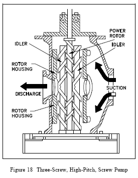
Screw pumps are a special type of rotary positive displacement pump in which the flow
through the pumping elements is truly axial. The liquid is carried between screw threads on one or more rotors and is displaced axially as the screws rotate and mesh

Centrifugal Pump


A centrifugal pump is a rotating machine in which flow and pressure are generated
dynamically. The inlet is not walled off from the outlet as is the case with positive displacement pumps, whether they are reciprocating or rotary in configuration. Rather, a centrifugal pump delivers useful energy to the fluid or “pumpage” largely through velocity changes that occur as this fluid flows through the impeller and the associated fixed passageways of the pump; that is, it is a “rotodynamic” pump

Pump classification

1. Dynamic
1.1 Centrifugal
1.1.1 Axial flow
1.1.1.1 Single stage
1.1.1.1.1 Close impeller
1.1.1.1.2 Open impeller

1.1.1.2 Multi stage
1.1.1.2.1 Close impeller
1.1.1.2.2 Open impeller

1.1.2 Mixed flow / Radial Flow
1.1.2.1 Single suction
1.1.2.2 Double suction

1.2 Special Effect
1.2.1 Jet (eductor)
1.2.2 Gas lift
1.2.3 Hydraulic ram
1.2.4 Electromagnetic

2. Displacement
2.1 Reciprocating
2.1.1 Piston, plunger
2.1.1.1 Steam - double acting
2.1.1.2 Power
2.1.1.2.1 Single acting
2.1.1.2.2 Double acting
2.1.2 Diaphragm
2.1.2.1 Simplex
2.1.2.1 Duplex
2.2 Rotary
2.2.1 Single rotor
2.2.1.1 Vane
2.2.1.2 Piston
2.2.1.3 Flexible member
2.2.1.4 Screw
2.2.1.5 Pristaltic

2.2.2 Multiple rotor
2.2.2.1 Gear
2.2.2.2 Lobe
2.2.2.3 Circumferential Piston
2.2.2.4 Screw

2-Column by Douglas Bowman |3 Column Blogger Template | Blogger-Hacks