Search

Custom Search

Tuesday, February 17, 2009

Pump selection and quality considerations

The following conditions should (explicitly or implicitly) be known in view of correctly selecting a pump:

  1.  task of the pump in the system.
  2. The system pressure and temperature.
  3. Data for rated performance: QR, HR,tot. Often rated performance equals the guaranteed point Qg, Hg. The rated and/or guaranteed performance may beidentical to the BEP (but this is not necessarily so).
  4. The NPSHA of the plant at rated, guaranteed or BEP conditions and, as necessary,at other operation conditions.
  5. Performance data for other specific operation points (if necessary).
  6. The maximum and minimum flow rates in the domain of continuous operation.
  7. The maximum and minimum flow rates during short-term operation or in transient conditions, e.g. during a switch-over of parallel working pumps, at load rejection or other.
  8. . For pumps operating in parallel the maximum flow rate (run-out) is determined by the operation of a single pump. At run-out the available NPSHA must be sufficient to prevent excessive cavitation.
  9. When pumps are installed in series, their interaction has to be analyzed with regard to control and upset conditions such as one pump falling out of service.
  10. The type and the chemical composition of the medium to be pumped, in particular corrosive substances.
  11. The physical properties of the pumpage if it is any other than water or a common, clearly defined medium. In this case the vapor pressure must be correctly specified in order to ensure that the effects and risks of cavitation can be assessed.
  12. Viscosities appreciably above that of cold water need corrections for Q, H, P,η and NPSH .
  13. Possible inclusions of free gas or dissolved gases that might separate from the liquid in the suction pipe.  The available NPSHA must be selected so that the volume fraction of free gas at the impeller inlet is below typically 2 to 4% at low suction pressures.
  14. Possible inclusions of solids (abrasion).
  15. The type of driver (electric motor, turbine, combustion engine).
  16. Fixed or variable speed? Speed range, if applicable.
  17. Is a gear box necessary?
  18. What kind of control is intended?
  19. How much standby capacity is required (e.g. 2x100% or 3x50% pumps)?
  20. Operation mode: Continuous or short-term operation? Cyclic operation with frequent start-ups and shut-downs?
  21. Installation conditions: Horizontal or vertical arrangement?
  22. Approach flow or suction conditions: Open or closed circuit? Open pit?
  23. Fluid level variations in the suction and discharge reservoirs or pressure variations on the suction and discharge side of the pumping system.
  24. The system characteristic or at least its static part Hstat resulting from the geodetichead differences and/or the pressure differences between the suction tank and the discharge vessel.
  25. Are there any special requirements concerning the head-capacity characteristic (steepness, head rise, shut-off pressure)?
  26. The maximum admissible shut-off pressure with the allowed tolerance, if applicable.
  27. For correctly sizing the driver, the maximum power consumption must be determined; with a small specific speed it occurs at about the maximum flow rate, with a medium nq near the BEP, and with very high specific speeds at shut-off.
  28. Are there any special requirements regarding vibrations or noise? Have limits been specified for the sound level?.
  29. What tolerances are permitted for manufacturing and measurements? Which standard is to be applied for the acceptance test?
  30. The guarantee and acceptance conditions, including possible penalties on efficiency or power consumption
  31. The operation period per year and the energy costs (e.g. $/kWh) or an assessment of the capitalized energy costs (e.g. $/kW). Minimization of the energy costs per year according to the intended operation scenarios.
  32. Safety considerations, explosion protection, zero-leakage to environment, ecological aspects.


Monday, February 16, 2009

Electric Motor Speed


The speed of an AC electric motor is determined by the frequency of the supply and the number of poles in the motor stator according to the following relationship:

where
n = speed (r/min)
f = supply frequency (Hz)
p = number of stator poles

From equation it can be seen that a change in frequency causes a change in speed. Electric motors can thus be speed regulated by means of varying the frequency

In Europe the frequency is 50 Hz, therefore the speed of electric motors is 6000 divided by the number of poles. At least two poles are required which produces a maximum speed of 3000r/min; 4 poles gives 1500; 6 gives 1000; 8 gives 750 r/min, etc. In the US and some Middle East countries as mentioned, the frequency is 60 Hz.

NPSH

Pump NPSH Requirement (NPSHR)
This figure is the necessary amount of energy required (measured in metres) in the liquid at the pump inlet to overcome the internal losses/resistances within the pump and provide sufficient internal pressure to avoid cavitation. These losses are caused by the flow of liquid through the pump suction passage and the shock loss which occurs at the impeller blade. The NPSHR is calculated by the pump manufacturer and will vary depending on the size and speed of the pump.

Available NPSH (NPSHA)
The available NPSH (NPSHA) is the amount of energy (measured in m) available to the fluid at the pump inlet after the factors from section 1 have been taken into account. For a pump to run the NPSHA value must be greater than the NPSHR value. The NPSHA value will govern the amount of suction lift which may be attained with a given pump or the amount of static suction head which is required above pump suction to ensure correct operation.

Hydraulic power

If a pump were an ideal machine, the required input power to drive the pump would
entirely lift the mass flow rate from one elevation to another. This power is called as the
hydraulic power.

Where
Q= capacity in m3 /h
ρ= liquid density in kg/m3 at pumping temperature
H= differential head in m (meters of liquid column)
g= gravitational acceleration in m/s .

Newtonian Fluid

A fluid is classified as being Newtonian if it conforms to NEWTON’s friction law, i.e. if viscosity remains constant with agitation or varying shear rate (i.e. viscosity is only affected by temperature changes) and its shear rate being proportional to the velocity gradient vertical to the direction of flow.

Of Newtonian fluid characteristics are e.g. the following:

water
oils
gases
mercury
alcohol
petrol

If it is not known whether a fluid is of Newtonian flow characteristics or not, it should be laboratory-tested."

Friday, February 13, 2009

Seismic Survey


The most accurate and widely used means of finding good drilling locations is the seismic survey. Seismic surveying involves sending sound waves down into the ground and recording the echoes that bounce back off the various sedimentary layers.The sound or shock waves are generated by; setting off small explosive charges just below the surface; hitting the ground with a heavy weight; or shaking the ground using large vibrator trucks. The echoes returning from the subsurface are detected by sensitive instruments called geophones which are strung out along the ground in a straight line. The geophones are connected by electrical cable to a recording system. The recording system precisely records, to the nearest one thousandth of a second on magnetic tape, the time it takes for the echoes to return to the surface. By knowing the amount of time it takes for a sound wave to reach a certain layer and then bounce back to the surface, as well as the speed of sound through the rock
layers in between, the geophysicist is able to determine the depth to that layer at that location. By determining the depth at a large number of points along the seismic line, the geophysicist is able to create a profile of the underground layers along the line.

Pump System Life Cycle Cost Reduction

The primary objective of life cycle costing is to evaluate and/or optimize product life cost while satisfying specified performance, safety, reliability, accessibility
maintainability, and other requirements. Pumping systems account for an estimated 25%-50% of the energy usage in many industrial plants, and perhaps 20% of the world’s electric energy demand. Centrifugal pumps rank first in failure incidents
and maintenance costs. That is why centrifugal pumps in critical applications are installed in identical pairs, one serving as the operating, the other one serving as the standby or spare pump. Despite these statistics, many pump purchase decisions
are still made solely on the basis of lowest initial purchase and installation cost. The notion exists that, if a cheap pump doesn’t perform well, it can always be
upgraded. While this may be true in those pumps that suffer from installation errors or component defects, it is not true for pumps that suffer from fundamental design
compromises. Moreover, these decisions seem to disregard that initial purchase price is generally only a small part of pump life cycle cost in high usage applications.
Market conditions, short-term financial considerations, and organizational barriers are to blame for this shortsighted approach.

LCC = Cic + Cin + Ce + Co + Cm + Cdt + Cenv + Cd
where:
LCC = Life Cycle Cost
Cic = Initial Cost, purchase price (pump, system,
pipe, auxiliary services)
Cin = Installation and commissioning cost
Ce = Energy costs (pump, driver & auxiliary services)
Co = Operation costs
Cm = Maintenance and repair costs
Cdt = Down time costs
Cenv = Environmental costs
Cd = Decommissioning and/or disposal costs

Thursday, February 12, 2009

Wellhead


The wellhead is equipment used to maintaain surface control of the well. It is usually made of cast or forged steel and machined to a close fit to form a seal and prevent well fluids from blowing or leaking at the surface.

Tuesday, February 10, 2009

Pump efficiency

The pump does not completely convert kinetic energy to pressure energy since some of the kinetic energy is lost in this process. Primarily, there are three areas where this energy is dissipated and not converted to useful work. Pump efficiency is a factor that accounts for these losses. Pump efficiency is a product of the following three efficiencies:

1. Hydraulic efficiency
(primarily, disk friction, which is the friction of the liquid with the impeller shrouds. This is a function of speed and impeller geometry. Other losses are shock losses during rapid changes in direction along the impeller and volute)

2. Volumetric efficiency
(recirculation losses at wear rings, interstage bushes and other)

3. Mechanical efficiency
friction at seals or gland packing and bearings). Some texts call the product of the first two efficiencies as internal efficiency of the pump. Every pump is designed for a specific flow and a corresponding differential head, though it is possible to operate at certain percentage points away from the designed values. However, the efficiency of the pump at the designed point is maximum and is called as the BEP. Efficiency at flows lower or higher than this design point is lower. The efficiency of the pump has a close relationship to an important pump number called as the specific speed.

Saturday, February 7, 2009

Centrifugal Pump Affinity Laws

The Affinity Laws of centrifugal pumps or fans indicates the influence on volume capacity, head (pressure) and/or power consumption of a pump or fan due to
change in speed of wheel - revolutions per minute (rpm)
geometrically similarity - change in impeller diameter

Note that the affinity laws for fans are not identical with pumps.
Pump Affinity Laws
Volume Capacity

The volume capacity of a centrifugal pump can be expressed like

q1 / q2 = (n1 / n2)(d1 / d2) (1)

where

q = volume flow capacity (m3/s, gpm, cfm, ..)

n = wheel velocity - revolution per minute - (rpm)

d = wheel diameter
Head or Pressure

The head or pressure of a centrifugal pump can be expressed like

dp1 / dp2 = (n1 / n2)2 (d1 / d2)2 (2)

where

dp = head or pressure (m, ft, Pa, psi, ..)
Power

The power consumption of a centrifugal pump can be expressed as

P1 / P2 = (n1 / n2)3 (d1 / d2)3 (3)

where

P = power (W, bhp, ..)

Sunday, February 1, 2009

API 610 Standard

Centrifugal pumps for petroleum, petrochemical and natural gas industries

IP (Ingress Protection) Codes


IEC 60529 outlines an international classification system for the sealing effectiveness of enclosures of electrical equipment against the intrusion into the equipment of foreign bodies (i.e., tools, dust, fingers) and moisture. This classification system utilizes the letters "IP" ("Ingress Protection") followed by two digits. (An "X" is used for one of the digits if there is only one class of protection; i.e., IP X4 which addresses moisture resistance only

ATEX directive


The ATEX directive is two EU directives describing what equipment and work environment is allowed in an environment with an explosive atmosphere.

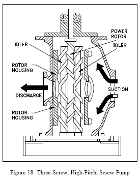
Screw pump


Screw pumps are a special type of rotary positive displacement pump in which the flow
through the pumping elements is truly axial. The liquid is carried between screw threads on one or more rotors and is displaced axially as the screws rotate and mesh

Centrifugal Pump


A centrifugal pump is a rotating machine in which flow and pressure are generated
dynamically. The inlet is not walled off from the outlet as is the case with positive displacement pumps, whether they are reciprocating or rotary in configuration. Rather, a centrifugal pump delivers useful energy to the fluid or “pumpage” largely through velocity changes that occur as this fluid flows through the impeller and the associated fixed passageways of the pump; that is, it is a “rotodynamic” pump

Pump classification

1. Dynamic
1.1 Centrifugal
1.1.1 Axial flow
1.1.1.1 Single stage
1.1.1.1.1 Close impeller
1.1.1.1.2 Open impeller

1.1.1.2 Multi stage
1.1.1.2.1 Close impeller
1.1.1.2.2 Open impeller

1.1.2 Mixed flow / Radial Flow
1.1.2.1 Single suction
1.1.2.2 Double suction

1.2 Special Effect
1.2.1 Jet (eductor)
1.2.2 Gas lift
1.2.3 Hydraulic ram
1.2.4 Electromagnetic

2. Displacement
2.1 Reciprocating
2.1.1 Piston, plunger
2.1.1.1 Steam - double acting
2.1.1.2 Power
2.1.1.2.1 Single acting
2.1.1.2.2 Double acting
2.1.2 Diaphragm
2.1.2.1 Simplex
2.1.2.1 Duplex
2.2 Rotary
2.2.1 Single rotor
2.2.1.1 Vane
2.2.1.2 Piston
2.2.1.3 Flexible member
2.2.1.4 Screw
2.2.1.5 Pristaltic

2.2.2 Multiple rotor
2.2.2.1 Gear
2.2.2.2 Lobe
2.2.2.3 Circumferential Piston
2.2.2.4 Screw

2-Column by Douglas Bowman |3 Column Blogger Template | Blogger-Hacks